In this post, I try to use digital logic to explain the basic concept of data routing.
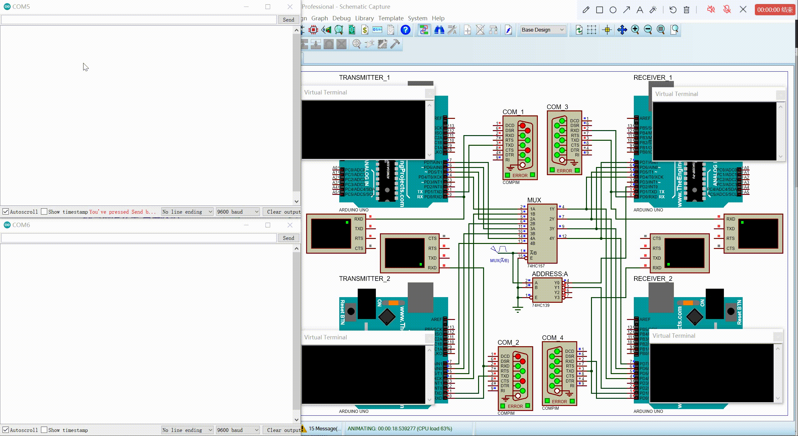
As we can see, in the circuit above, there are two transmitters 1&2 and two receivers 1&2. Relationship’s as follows.
1 | Transmitter_1 -- Receiver_1 |
Because there are four bits outputs for each transmmiter, we need at least 8-bit lines when connect them seperately.
But if we use MUX(74HC157) and Decoder(74HC139) to connect them, we just need 4-bit lines. (Here we can ignore all the controlling bus, such as the lines from the decoder, because we can do that when the amount of transmitters and receivers increases to a huge number.) The two Transceiver Pairs will share the outputs of the MUX, if we can handle the sequence of the clock well.
Of couse we also need a DEMUX to distribute the datas to the right destination. Unlike the MUX in the circuit, which is hardware, I use External Inerrupt(INT0) of Arduino UNO to respond to the controlling signal of the Decoder. I call it a soft demux.(I can’t find a proper 74 series demux which has double four-bit outputs.)
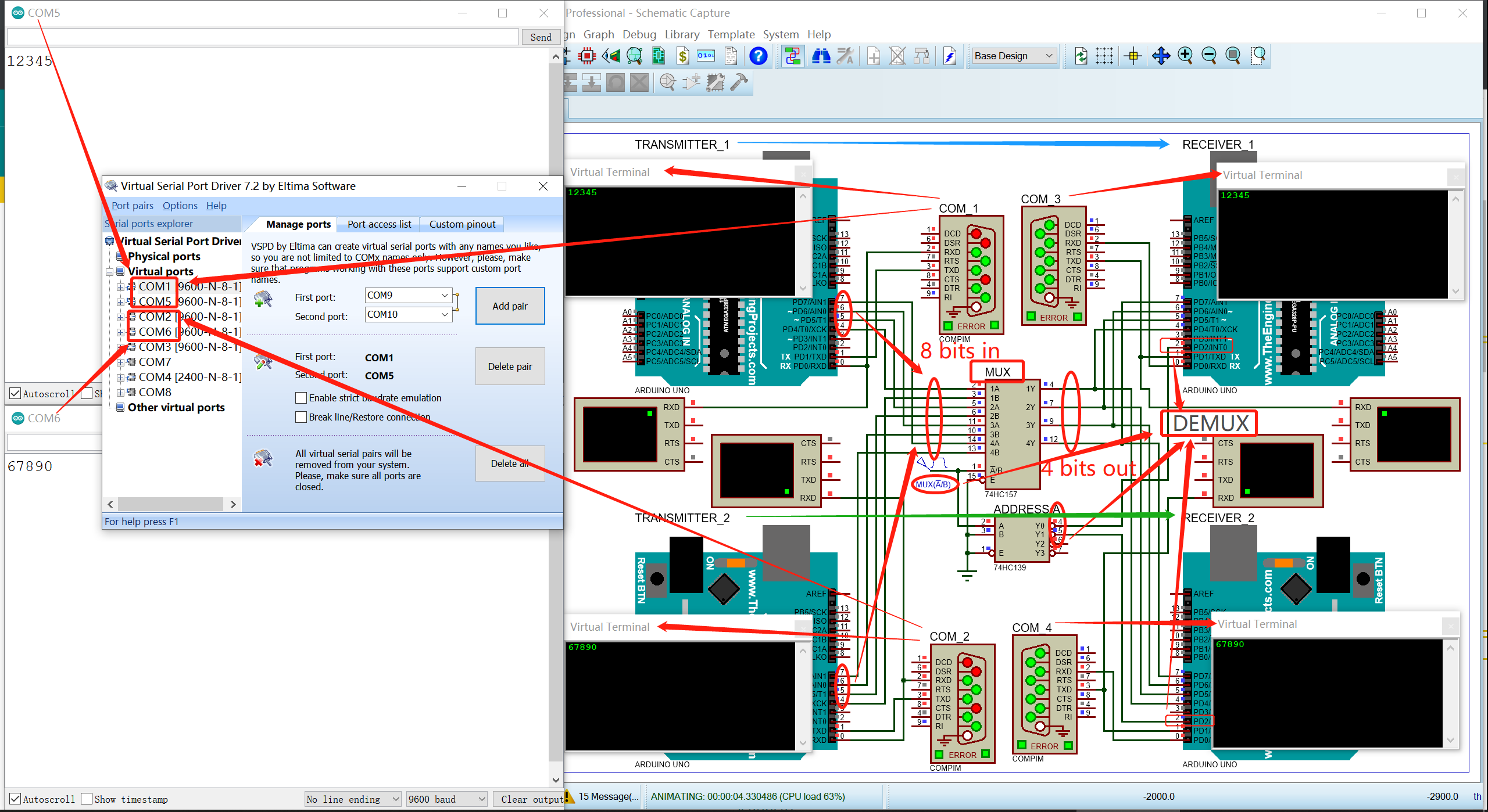
The Virtual Serial Port Pairs Map is:
1 | COM1--COM5 |
COM1: Port of Transmitter_1
COM2: Port of Transmitter_2
COM5: Port of Arduino IDE Serial Monitor_1
COM6: Port of Arduino IDE Serial Monitor_2
tip: only four serial port supported in Proteus
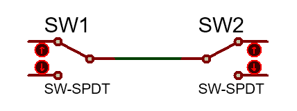
Finally, the concepts of switching, routing, multiplexing and demultiplexing, whatever you name them, SPDT is their prototype in my opinion.