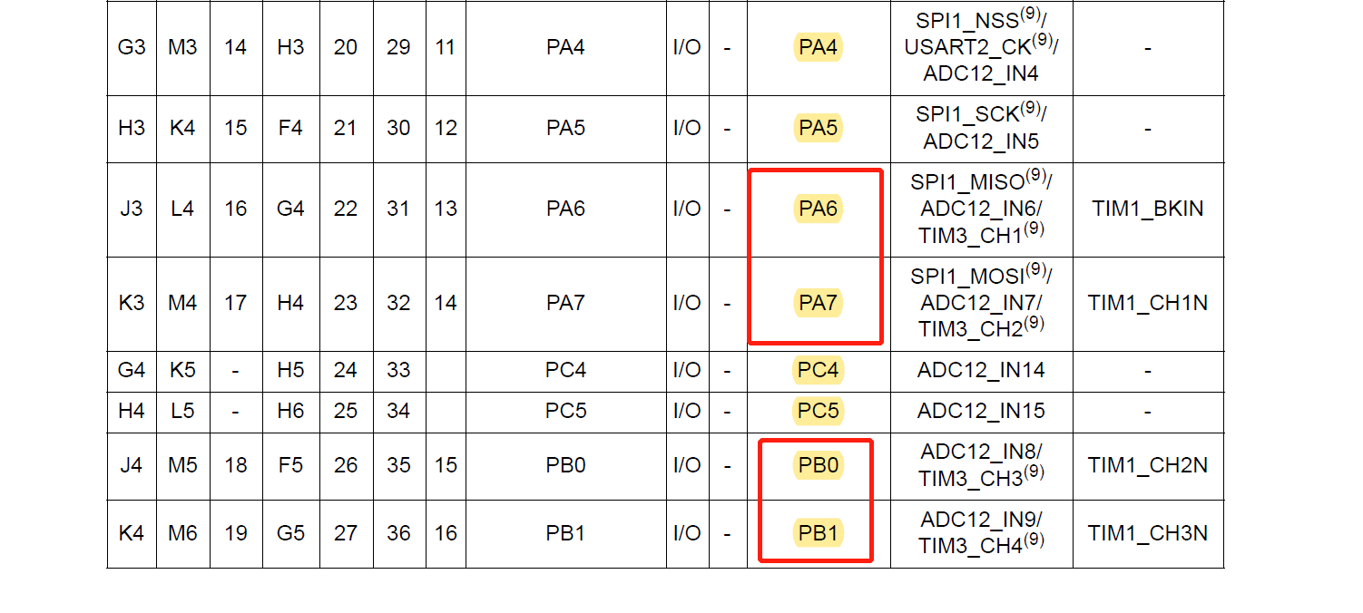
When configuring TIM3 as a PWM generater, CH1-CH4 are PA6, PA7, PB0, PB1.
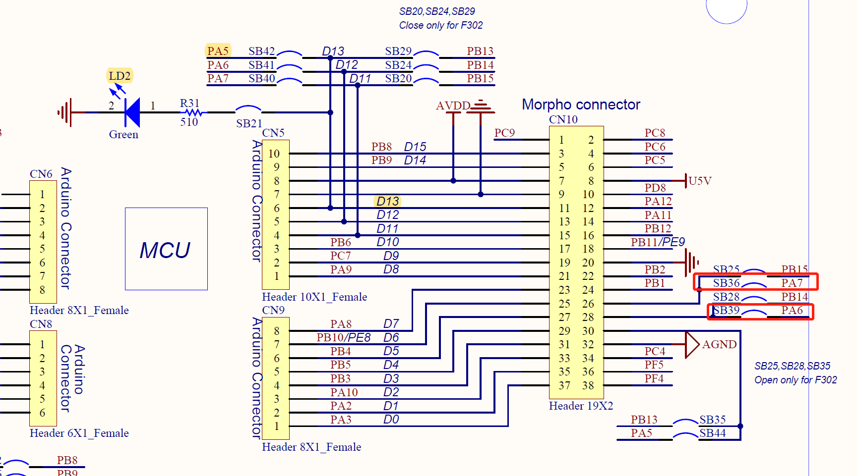
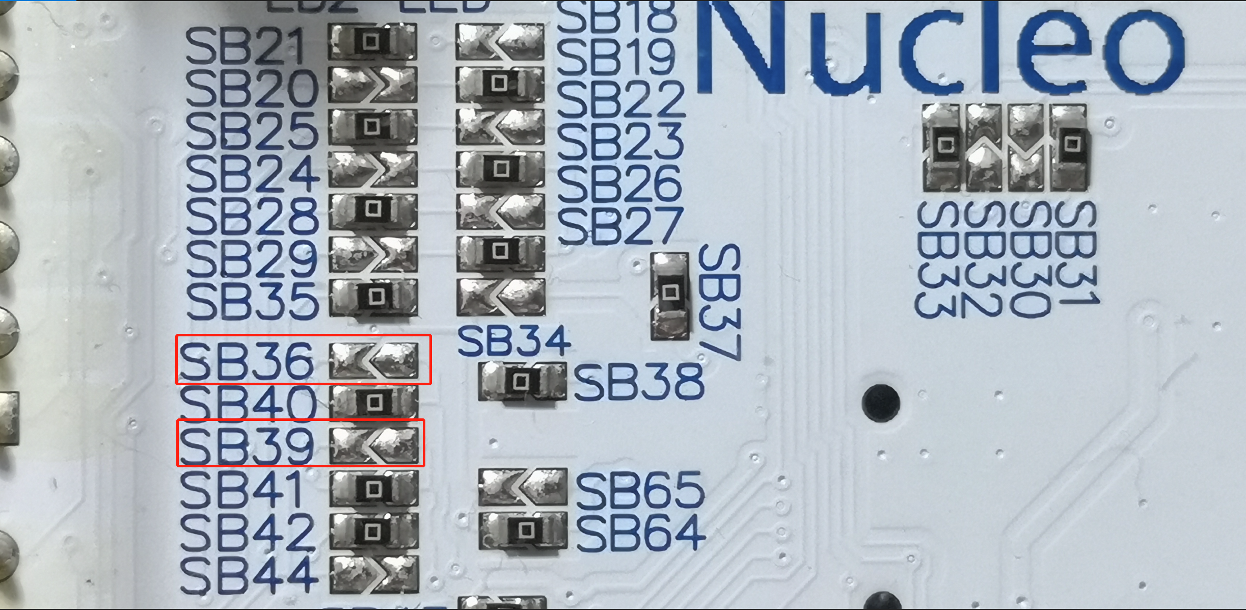
Eventhough all the above four pins have been lead out on nucleo, 0 ohms resistors of PA6 and PA7 remain unsoldered by default. We must find another way to generate the other 2 PWM if we don’t want to solder SB36 and SB39.
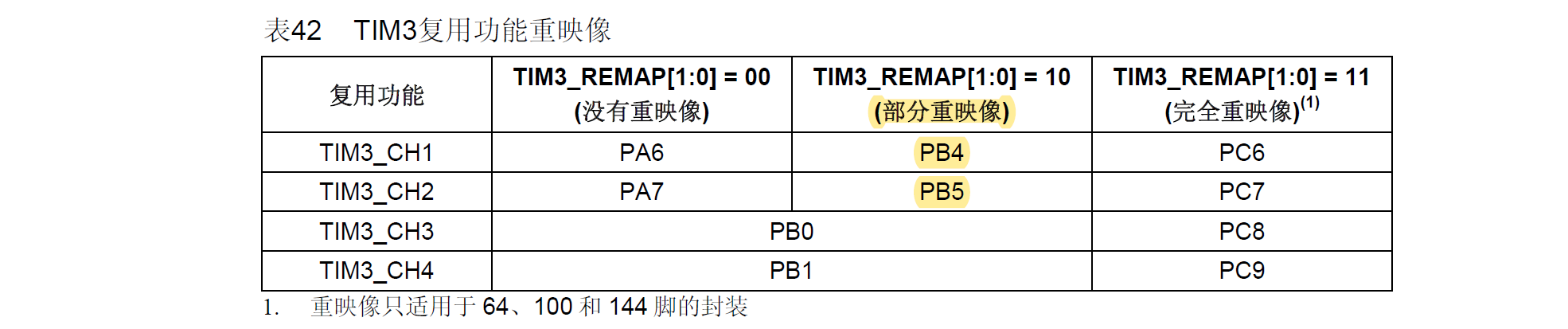
Like FPGA, some pins(not all) of stm32f10x can be remapped to each other. We can use “fullremap” to remap CH1-CH4 to PC6-PC9 or “partialremap”, only PA6-PA7 to PB4-PB5.(I also tried the latter, PB5 worked but PB4 still didn’t. Don’t know why.)
1 | RCC_APB2PeriphClockCmd(RCC_APB2Periph_GPIOC, ENABLE); |
Finally I got all PWM, but still don’t understand why PB4 malfunctions. Maybe need read UM1724 again and again. Sugar cane is not sweet at both ends. Now that we enjoyed the convennience of finished hardware, we must accept the limitition of it and try our best to read the user’s manual and rack our brains to find an alternative method.